Scale
A lower BoM in every HV battery pack, from one rack to a gigawatt-hour.
The edge devices carry no MCU, and the battery logic runs in each rack’s Central BMS. The saving repeats with every HV battery pack added.


One rack
400 kWh
8 HV battery packs in one rack, under its Central BMS.
A conventional BMS
24
MCUs in the HV battery packs, each with firmware of its own
Edge devices
0
MCUs in the edge devices. The battery logic runs in the Central BMS.
One container
4.8 MWh
96 HV battery packs in 12 racks, and a Central BMS in each rack.
A conventional BMS
288
MCUs in the HV battery packs, each with firmware of its own
Edge devices
0
MCUs in the edge devices. The battery logic runs in the 12 Central BMSs.
Ten containers
48 MWh
960 HV battery packs in 120 racks, and a Central BMS in each rack.
A conventional BMS
2,880
MCUs in the HV battery packs, each with firmware of its own
Edge devices
0
MCUs in the edge devices. The battery logic runs in the 120 Central BMSs.
A grid-scale site
1 GWh
20,000 HV battery packs in 2,500 racks, and a Central BMS in each rack.
A conventional BMS
60,000
MCUs in the HV battery packs, each with firmware of its own
Edge devices
0
MCUs in the edge devices. The battery logic runs in the 2,500 Central BMSs.
Illustrative. 50 kWh in each HV battery pack, eight HV battery packs to a rack, twelve racks to a container, and three MCUs in each HV battery pack with a typical conventional BMS.
Cells
Change the cells. Keep the BMS.
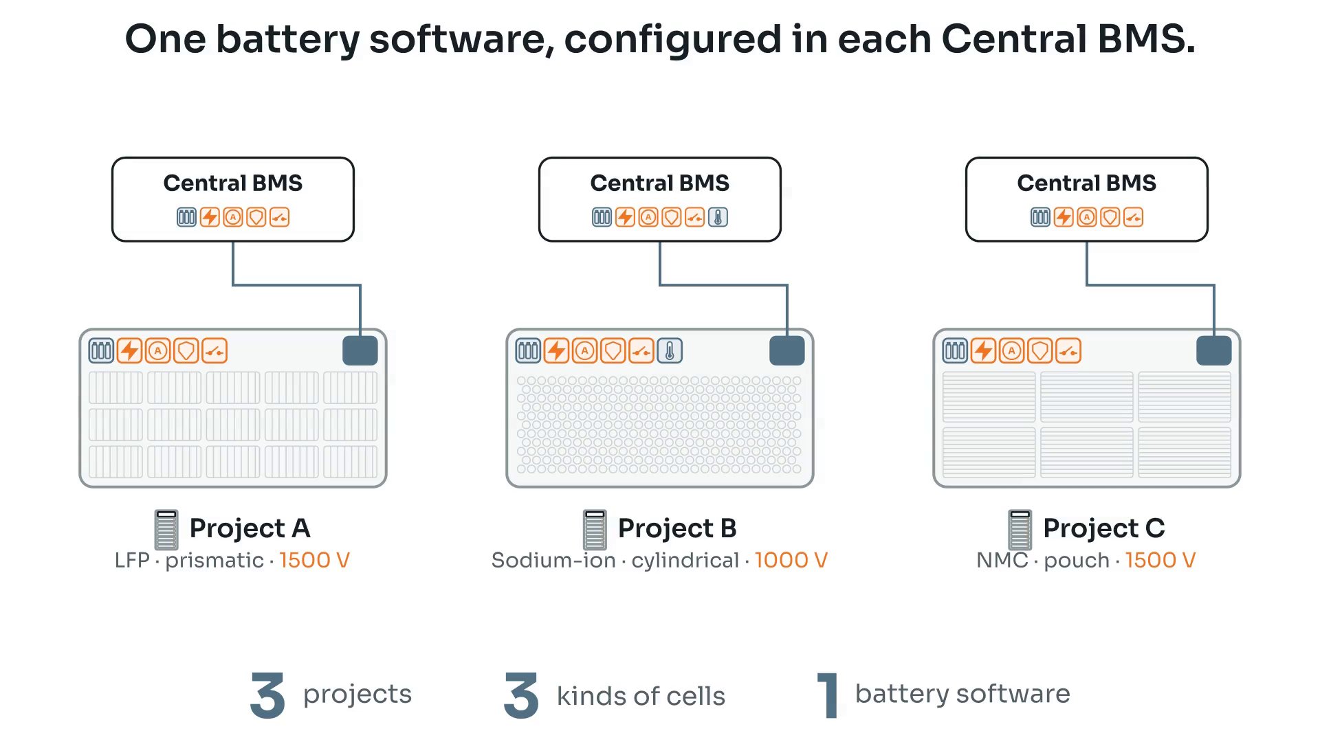
Each project can take its cells from a different supplier, chemistry or voltage class. The battery software stays the same, configured in each Central BMS.
Monitoring
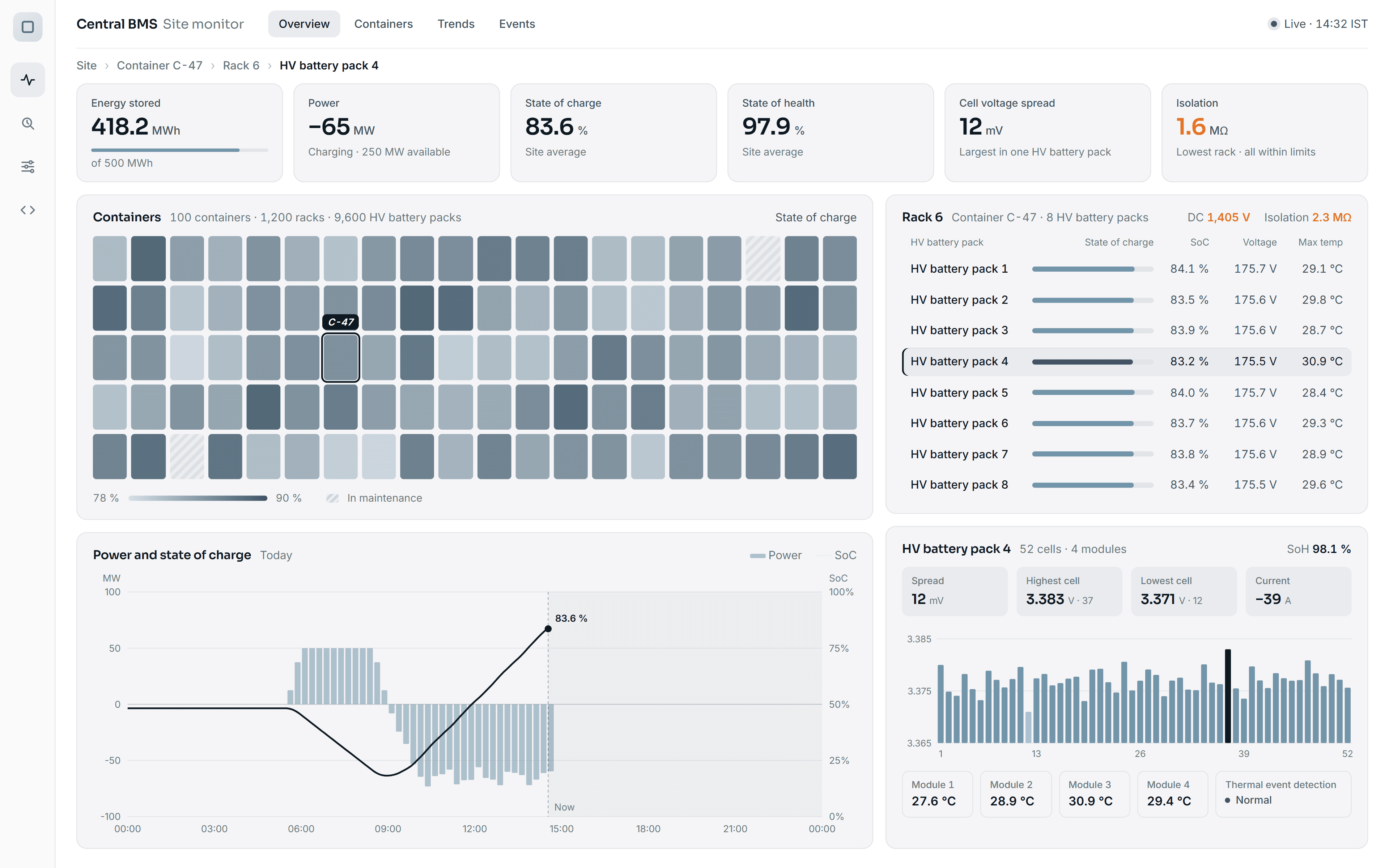
Ethernet from every HV battery pack, and every cell in view.
Each HV battery pack connects over Ethernet to its rack’s Central BMS, without needing a gateway. Every reading reaches it, so a site is monitored down to each cell, and a fault is traced to the edge device that raised it.
Questions storage integrators ask
Which standards is the BMS designed for?
IEC 61508 for functional safety, each edge device to the SIL it needs, and the BMS requirements of IEC 62619 and UL 1973, so the system it runs in can meet them.
Which voltage class does it suit?
Up to 1500 V, the voltage class of large storage systems. Isolation is monitored continuously while the system runs.
What happens if communication is lost?
The BMS is designed to reach a safe state.
Where does the battery software run, and who owns it?
In each rack’s Central BMS, which is the integrator’s own. The device drivers come with the edge devices, and the integrator’s battery algorithms run on top.
Can thermal event detection be added later?
Yes. A thermal event monitor in each module plugs in as one more edge device, when a project asks for it, and is configured in the Central BMS.